|
|
Post by admin on Aug 30, 2019 17:22:05 GMT
|
|
|
|
Post by kostet2010 on Dec 9, 2019 17:20:31 GMT
radikal.ru/video/pQpDv8OEETTя собрал на jeep wrangler tj 98. электронную цифровую панель приборов. мне нужно устройство которое может прочитать ccd bus панели приборов.
|
|
|
|
Post by kostet2010 on Dec 22, 2019 13:32:18 GMT
Hello. I really need this device, but $ 150 is very expensive for me. I have Arduino Mega and FT232RL FTDI. Can I assemble such a device myself? help me please.
|
|
|
|
Post by admin on Dec 25, 2019 10:08:28 GMT
Hi! I see you only need a CCD-bus interface. You'll need this interface chip to convert CCD-bus communication to serial that Arduino can understand: www.ebay.com/itm/153170890038Get a breadboard too, a few resistors and set it up according to this schematic: github.com/laszlodaniel/ChryslerCCDSCIScanner/raw/master/PCB/V142/ChryslerCCDSCIScanner_V142/schematic/ChryslerCCDSCIScanner_V142_schematic.pdfOnly consider the "CCD-bus interface" section. I have to adjust a few things in the firmware but it should run on an Arduino Mega board as it is. Let me know how things go and I can give further help. Edit: the standalone bias is not necessary for you, so you can skip those 3 resistors and the 2 jumpers they connect to. Edit 2: wiring CDP68HC68S1E-----------Arduino Mega
Pin 1 (CLK, 1MHZ)------Pin 11
Pin 8 (XMIT)-----------Pin 18 (TX1)
Pin 9 (REC)------------Pin 19 (RX1)
Pin 12 (IDLE)----------Pin 2 (INT4) + 10kOhm pullup to +5V
Pin 13 (CTRL)----------Pin 3 (INT5) + 10kOhm pullup to +5V |
|
|
|
Post by kostet2010 on Jan 8, 2020 1:42:47 GMT
<ya-tr-span data-index="90-0" data-value="в панели приборов есть нужные детали? " data-translation="в панели приборов есть нужные детали? " data-type="trSpan">в панели приборов есть нужные детали? </ya-tr-span>  |
|
|
|
Post by kostet2010 on Jan 10, 2020 14:08:37 GMT
я заказал CDP68HC68S1E
|
|
|
|
Post by admin on Jan 12, 2020 15:49:17 GMT
Yes, the dashboard has a Philips IC (4632650) on the top, that's the CCD-bus controller. The CDP68HC68S1E can receive its messages and you can send messages to it too. My BCM has the same Philips IC and communication is good. 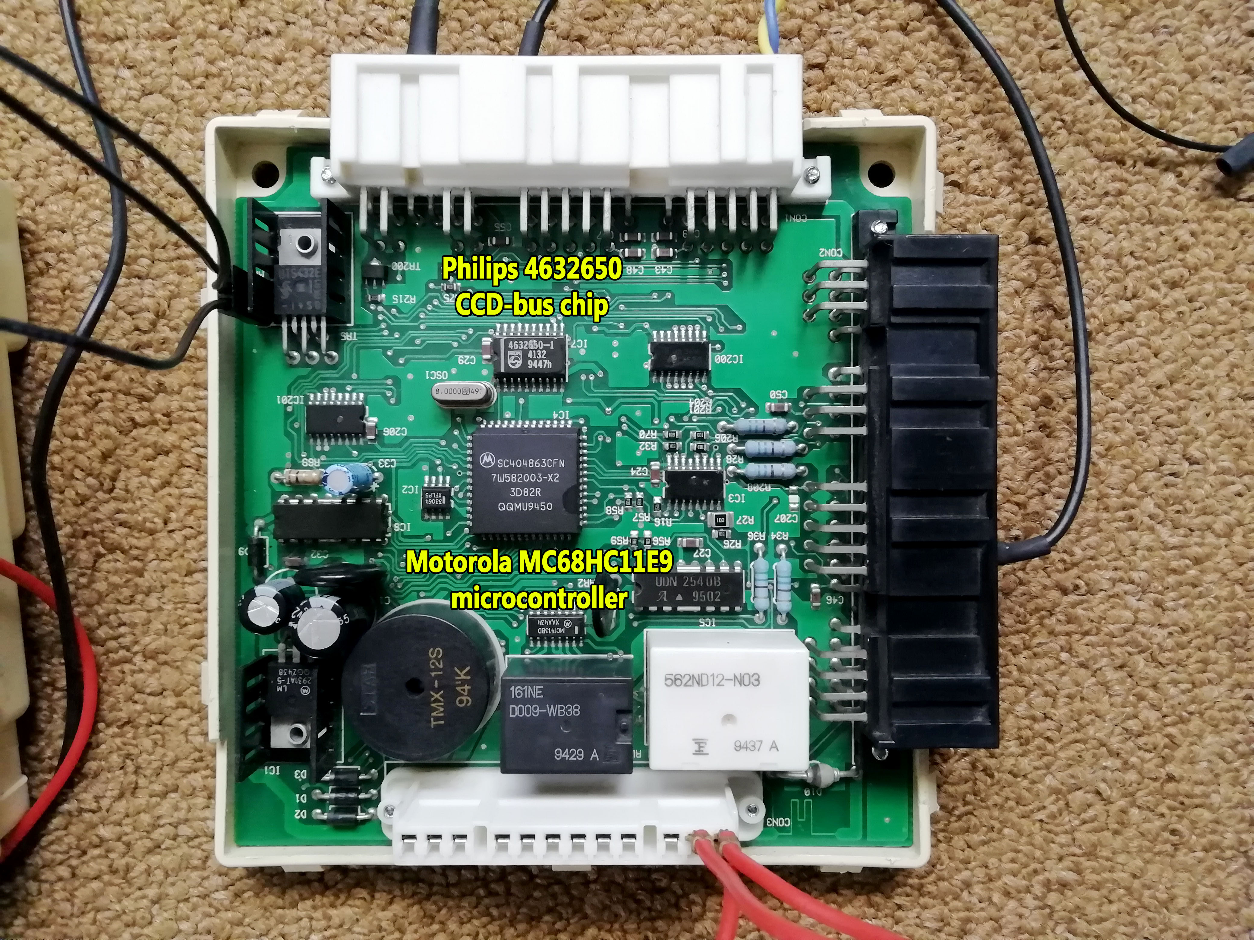 Edit: CCD-bus voltage biasing and termination may be necessary after all. Previously I said you won't need those 3 resistor but if the CCD-bus won't come online that's the reason why. So keep an eye on it when you test it. |
|
|
|
Post by kostet2010 on Jan 14, 2020 3:54:05 GMT
смысл такой. я собрал себе цифровую панель приборов на ардуино. ардуино является блоком сбора данных(от нее идут провода к датчикам и лампочкам).потом ардуино передает информацию на андроид (khadas vim) по кабелю Ethernet.а андроид уже выводит видео на матрицу. я хочу перевести эту панель приборов на ccd bus ,чтобы избавиться от половины проводов.скетч в ардуино я перепишу. так вот мне нужно устройство которое будет отсылать запросы в шину, получать ответы и передавать их в ардуино.вы можете нарисовать схему такого устройства.или сделать его(цена)?https://radikal.ru/video/pQpDv8OEETT
|
|
|
|
Post by admin on Jan 20, 2020 18:03:07 GMT
All the wiring is in the schematics. The code running on the Arduino Mega however has to be tailored for your needs. For basic CCD-bus communication you can copy my code on GitHub and extend it.
|
|
|
|
Post by kostet2010 on Mar 4, 2020 16:14:29 GMT
|
|
|
|
Post by kostet2010 on Apr 3, 2020 14:54:00 GMT
я все спаял. подсоединился к ccd-bus приборной панели.панель работает - пакетов в мониторе нет.
|
|
|
|
Post by admin on Apr 5, 2020 6:59:26 GMT
Alright.
Please try this simplified CCD-bus monitor code to make sure the CCD-bus chip works (Arduino Mega only).
Use the Arduino IDE's serial monitor to view CCD-bus messages.
I modified the wiring instructions to include every connection.
Make sure to connect vehicle battery ground to Arduino ground too. Without common ground logic levels are undetermined.
/*
Wiring:
CDP68HC68S1E-----------Arduino Mega
Pin 1 (CLK, 1MHZ)------Pin 11
Pin 2, 3 (A, B)--------GND
Pin 4 (MODE)-----------+5V
Pin 5 (BUS+)-----------
Pin 6 (BUS-)-----------
Pin 7 (GND)------------GND
Pin 8 (XMIT)-----------Pin 18 (TX1)
Pin 9 (REC)------------Pin 19 (RX1)
Pin 10 (SCK)-----------no connect
Pin 11 (CS)------------+5V
Pin 12 (IDLE)----------Pin 2 (INT4) + 10kOhm pullup to +5V
Pin 13 (CTRL)----------Pin 3 (INT5) + 10kOhm pullup to +5V
Pin 14 (VCC)-----------+5V
*/

bool ccd_idle = false;
uint8_t ccd_msg_length = 0;
uint8_t data_byte = 0;

void ccd_eom(void)
{
    ccd_idle = true; // set idle flag
}

void setup()
{
    Serial.begin(250000); // enable Serial 0 monitor

    // Set Serial 1 speed to 7812.5 baud
    UBRR1H = (127 >> 8) & 0x0F;
    UBRR1L = 127 & 0xFF;

    // Enable Serial 1 receiver and transmitter
    UCSR1B |= (1 << RXEN1) | (1 << TXEN1);

    // Set frame format: asynchronous, 8 data bit, no parity, 1 stop bit
    UCSR1C |= (1 << UCSZ10) | (1 << UCSZ11);

    // Start 1 MHz clock on Pin 11
    TCCR1A = 0;                        // clear register
    TCCR1B = 0;                        // clear register
    TCNT1  = 0;                        // clear counter
    DDRB   |= (1<<DDB5);               // set OC1A/PB5 as output
    TCCR1A |= (1<<COM1A0);             // toggle OC1A on compare match
    OCR1A  = 7;                        // top value for counter, toggle after counting to 8 (0->7) = 2 MHz interrupt ( = 16 MHz clock frequency / 8)
    TCCR1B |= (1<<WGM12) | (1<<CS10);  // CTC mode, prescaler clock/1 (no prescaler)

    attachInterrupt(digitalPinToInterrupt(2), ccd_eom, FALLING); // execute "ccd_eom" function if the CCD-transceiver pulls D2 pin low indicating an "End of Message" condition
}

void loop()
{
    if (ccd_idle)
    {
        ccd_idle = false;
        ccd_msg_length = Serial1.available();

        for (uint8_t i = 0; i < ccd_msg_length; i++)
        {
            data_byte = Serial1.read(); // read one byte from CCD-bus buffer
            if (data_byte < 16) Serial.print("0"); // leading zero
            Serial.print(data_byte, HEX);
            Serial.print(" ");
        }

        Serial.println(); // new line
    }
}
From your PM:
I don't exactly understand what you are trying to do.
|
|
|
|
Post by kostet2010 on Apr 10, 2020 17:57:55 GMT
я хочу на приборную панель отправлять пакеты данных от00 до ff,чтобы понять какой покет за что отвечает
|
|
|
|
Post by rubensx on Apr 10, 2020 18:15:14 GMT
hi Daniel! great work with the scanner, I'm from brazil and gonna make a copy from your project to test... As I understand, kostet2010 create same board only with arduino mega and philips ccd bus chip from a old cluster?
and Kostet, how you make te lcd cluster? can you explain the hardware and software what are use?
thank you guys
|
|
|
|
Post by rubensx on Apr 10, 2020 18:28:47 GMT
I have a jeep xj 2000 here in brazil and has intent to mod the cluster too (I've a spare cluster too and can shield arduino and odroid C2 board) and maybe I can help! To my old honda ej1 I'm creating a odroid c2 board with realdash, what dash are you using and arduino communicate with elm327 or somenting else?
|
|